Blog
Why FEA Analysis in CAD Is Essential for the Modern Engineer

Simulation Instead of Trial and Error: Why FEA Analysis in CAD Is Essential for the Modern Engineer
In modern mechanical engineering and industrial design, the time between an idea and a finished product comes at a high cost. The traditional approach of “build a prototype, test it, break it, redesign it” is gradually becoming obsolete. Instead, engineers increasingly rely on virtual testing during the 3D modeling stage.
One of the key technologies enabling this shift is Finite Element Analysis (FEA). But what exactly is FEA, and why should every design engineer incorporate it into their daily workflow? Let’s take a closer look.
What Is FEA Analysis?
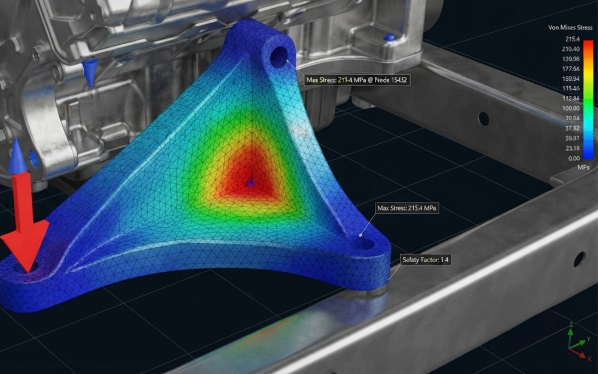
Every 3D model created in a CAD system consists of solid geometry. Finite Element Analysis divides this complex geometry into thousands—or even millions—of small, simple elements connected by nodes, forming what is known as a mesh.
The software calculates how each individual element behaves under specified loads such as forces, pressure, temperature, or vibration. It then combines these calculations into a complete picture of the stresses, strains, and deformations throughout the entire model.
This allows engineers to identify structural weaknesses long before a single gram of material is used to manufacture a physical prototype.
Key Benefits of FEA in CAD
Integrating simulation tools directly into modern CAD software provides several significant advantages:
Save Time, Materials, and Costs
Instead of relying on excessive safety margins that make products heavier and more expensive, FEA enables engineers to optimize geometry intelligently. Material can be removed from low-stress areas while reinforcing critical regions where additional strength is required.
Accelerate Product Development
Virtual simulations can be completed within minutes or hours, whereas manufacturing and testing physical prototypes often takes weeks or even months.
Improve Safety and Reliability
FEA makes it possible to simulate extreme operating conditions, overloads, impacts, thermal effects, and vibration scenarios that may be difficult, costly, or unsafe to reproduce in real-world testing.
Faster Design Iterations
Need to modify a wall thickness or increase a fillet radius? In a parametric CAD model, these changes can be applied instantly, allowing the mesh and simulation results to update with just a few clicks.
Where Is FEA Most Commonly Used?
Mechanical Engineering and Heavy Industry
FEA is widely used to evaluate the structural integrity and fatigue life of machine frames, gearbox housings, shafts, welded structures, and mechanical assemblies.
Aerospace and Automotive Engineering
Engineers use FEA to analyze chassis deformation, suspension components, crash performance, vibration behavior, and overall structural durability.
Product Design and Plastic Components
Simulation helps validate plastic parts through virtual drop tests while identifying stress concentrations around snap-fits, ribs, mounting points, and other critical features before tooling begins.
Conclusion
FEA analysis in CAD is far more than colorful stress contour plots—where red typically indicates high stress and blue represents lower stress levels. It is a powerful engineering validation tool that transforms design decisions from educated assumptions into data-driven engineering.
By integrating simulation into the product development process, engineers can create lighter, stronger, safer, and more competitive products while significantly reducing development time and manufacturing costs.
In today’s technology-driven world, the companies that succeed are those capable of predicting product performance long before the CNC machine starts cutting—or the 3D printer begins printing.